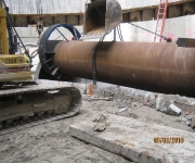
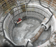
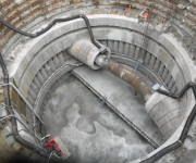
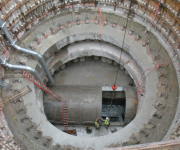
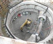
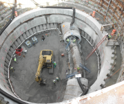
Description: Construction of (4) Control/Access Structures and (1) Control Access Pump Station, (4) of the (5) structures are cylindrical and (1) is rectangular. Three of the five structures are aligned within the International Transmission Co. (ITC) corridor.
Control structures (CS) 5, 6, 8 & 9 are constructed within two stage temporary circular earth retention systems and range in diameter from 24′ I.S. to 72′ I.S. with depths ranging to 100′ below grade. CS-7 has a rectangular temporary earth retention system 24’x34′ I.S. diameter and is 54′ below grade. Each CS is to receive reinforced cast-in-place concrete control/access structures:
- Design-built cementitious/bentonite and chemical (Sodium Silicate) soil grouting to stabilize loosen soils, depths ranging from 50′ to 75′ total cementitious/bentonite grouting was 265 cyd’s.
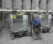
- Control structures 5,6,7 & 9 (CS) required extensive temporary dewatering systems. CS-5 & 6 were design-built deep gravity wells which were supplement with educator wells or vacuum well systems. Dewatering systems ranged from 92’to 113′ deep. CS-7required deep gravity wells and educator well system 60′ to 90′ deep. CS-9 required deep gravity wells 125′ below grade.
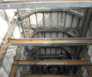
- Temporary Earth Retention Systems (TERS) (3) CS were two stage, (2) were single stage. Upper TERS were steel ribs with hard wood lagging and Lower TERS were 3′ diameter tangent piers filled with cement stabilized flyash with w18 x 150-175# soldier pile. Tangent piers were installed from -50′ from grade to 71′ depths.
- Dry and wet weather flow in the the existing interceptors must be maintained. Project involved work within the interceptors while maintaining flows; temporary flume structures and bulkheads were required at each CS. Interceptor ranged from 8’9″ to 12′ 9″ I.D.
Associated Infrastructure consisted of the following:
- ITC Transmission Towers and Transmission Line overhead requirements with safety requirements with clearance and sag due to temperature changes.
- Flow Management provided uninterrupted sanitary sewage service to all communities within the OMID Drainage District at all times.
- Demolition of existing interceptor while maintaining sewer flows via temporary flume was required to allow construction of new Control Structures.
Special Notes:
- Design-built temporary flume structures within existing interceptor sewer systems including associated temporary bulkheads; flumes were installed under dry and wet weather flows. Interceptor flow was +/- 300 CFS.
- Ground Settlement at CS within the ITC was critical, settlement at TERS and the ITC towers were monitored bi-weekly for ground settlement.
